View Attributes dialog, Building panel Application tabs
When a Building
Dynamic View is created, drawing rules are exposed in the three
View Attributes dialog, Building panel application
tabs. Use the application
tabs to manage and prioritize rule definitions that are available for use.
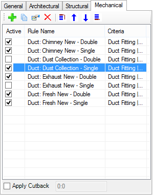
Remember: Drawing rules are applied in the
order in which they appear in the Building application tab. Resulting
resymbolization of Building elements may differ based on the order of drawing
rules in the list. Use the
"move to" controls to manipulate the rules order.
| Setting | Description |
|---|---|
 (Attach)
|
Opens the Apply Drawing Rules dialog . Select a drawing rule in the Apply Drawing Rules dialog, click the Add To View, and the rule is added to the Building application tab drawing rules list box. |
 (Copy)
|
Creates a copy of the selected rule in the Building application tab, creating a second entry. Typically, the second entry (copy) is edited in its originating drawing rule creation dialog via the Apply Drawing Rule dialog. |
 (Modify)
|
Opens the Apply Drawing Rules dialog where rule criteria can be modified and the selected rule is updated. |
 (Detach)
|
Removes the selected rule from the Building application tab drawing rules list box. Detaching a rule does not delete the rule definition. |
 Move First
|
Moves a selected drawing rule up to the top of the Building application tab drawing rules list box. The rule is listed first and it is the first rule applied. |
 Move Up
|
Each click of the icon moves a selected drawing rule up, one row toward the top, in the Building application tab Drawing rules list box. |
 Move Down
|
Each click of the icon moves a selected drawing rule down, one row toward the bottom, in the Building application tab drawing rules list box. |
 Move Last
|
Moves a selected drawing rule down to the bottom of the Building application tab drawing rules list box. The rule is listed last and it is the last rule applied. |
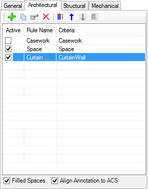
| Drawing Rules list box | Displays rule names, rule criteria, and active status. The list populates the following columns as drawing rules are added. |
| Filled Spaces | When on, all spaces in building dynamic views are filled with the space’s element color. When off, spaces are displayed in wire frame. |
| Align Annotation to ACS | When on, the DataGroup annotation text and column grid bubbles align to the current ACS in the promoted view. |
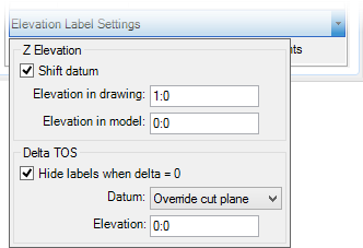
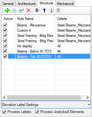
| Elevation Label Settings |
Z Elevation settings appear when a
drawing rule is selected which contains a top/bottom end 1 or 2 of section
(TOS, BOS, TOS1, TOS2, BOS1, BOS2) and/or a delta top end 1 or 2 of section
(DTOS, DTOS1, DTOS2) custom label attribute. These attributes display the
elevations at the member's section extremities as opposed to its placement
point.
|
| Process Labels | When on, labels present in the Structural model are processed. |
| Process Analytical Elements | When on, analytical elements present in the Structural model are processed. |
| Apply Cutback | Sets cutback value that applies a setback on the resymbolized geometry of the lower component when ducts or pipes are crossing each other in an elevation. |